Abstract
Extraforaminal spinal nerve stimulation (SNS) is an emerging neuromodulation technique for treating neuropathic pain. Targeting the spinal nerve distal to the intervertebral foramen enables anatomically precise stimulation, distinguishing it from conventional spinal cord or dorsal root ganglion stimulation. This article provides the first comprehensive description of the extraforaminal SNS approach, including technical refinements, anatomical insights, and clinical experience. Key procedural steps include identifying anatomical landmarks, intraoperative stimulation strategies, and lead placement guidance. A central feature of the technique is using intraoperative motor stimulation to confirm accurate lead positioning, evidenced by visible, low-threshold muscle contractions. Tonic stimulation was employed to assess dermatomal coverage. Stimulation was applied intraoperatively and postoperatively to guide and confirm lead positioning. Two modified anchoring techniques were developed and implemented to address the challenge of lead migration; since their adoption, no further cases of lead dislocation have been observed. The described approach has proven safe, feasible, reproducible, and effective in clinical practice. Extraforaminal SNS offers a focused, segment-specific neuromodulation strategy for patients with localized dermatomal pain in the lower extremity, particularly for those with contraindications to conventional neurostimulation modalities. Its advantages include a shallow learning curve, precise anatomical targeting, reliable intraoperative stimulation, and improved long-term lead stability through robust conventional spinal cord stimulation systems combined with optimized anchoring techniques. These characteristics support its growing clinical relevance as a technically straightforward and effective alternative to traditional stimulation methods in selected patient populations. This article provides detailed guidance on the successful implementation of this technique for the treatment of therapy-resistant neuropathic pain.
Keywords
Extraforaminal spinal nerve stimulation, Neuromodulation, Chronic neuropathic pain, Peripheral nerve stimulation
Abbreviations
SCS: Spinal Cord Stimulation; DRG: Dorsal Root Ganglion; PNS: Peripheral Nerve Stimulation; SNS: Spinal Nerve Stimulation; DRG-S: DRG Stimulation; IPG: Implantable Pulse Generator; CRPS: Complex Regional Pain Syndrome; PSPS: Persistent Spinal Pain Syndrome; FAST: Fast-acting Subperception Therapy
Introduction
Spinal neuromodulation has significantly advanced in recent decades, expanding beyond traditional dorsal column stimulation to include techniques targeting the dorsal root ganglia (DRG) and peripheral nerves [1–3]. A notable innovation in this field is spinal nerve stimulation (SNS) using an extraforaminal approach, a specialized peripheral nerve stimulation (PNS) where electrodes are positioned laterally to the intervertebral foramen, near the spinal nerve [4].
This method delivers highly focal stimulation to individual spinal nerves, particularly beneficial in chronic, focal, mono-radicular pain such as radiculopathy and foraminal stenosis [4]. Additionally, it addresses neuropathic pain related to nerve lesions in the lower extremities, groin pain, knee pain post-knee replacement, and complex regional pain syndrome [4,5]. Compared to traditional spinal cord stimulation (SCS), extraforaminal SNS offers potentially more precise dermatomal coverage with reduced risk of unintended stimulation in non-target areas. It also provides a safe extraforaminal and minimally invasive access route compared to DRG stimulation (DRG-S). It is especially advantageous in complex cases where DRG lead implantation is not feasible or contraindicated.
An additional advantage over classical PNS is that extraforaminal SNS is not limited to the sensory territory of a single peripheral nerve. Instead, it can cover an entire dermatome by directly targeting the corresponding spinal nerve [4]. This enables more anatomically comprehensive and dermatomally precise coverage, particularly in cases where pain extends beyond the domain of a single nerve or involves multiple overlapping territories.
Moreover, this method does not require a dedicated or proprietary stimulation system. It can be implemented using conventional implantable SCS/PNS pulse generators (IPG) and leads, simplifying device compatibility and improving clinical accessibility [4].
Our study builds upon previous research demonstrating this technique's safety and long-term efficacy in over 70 cases spanning five years. No intraoperative complications were observed within this cohort, underscoring the procedural safety. Postoperative complications were limited primarily to lead migration, which required revision in approximately 20% of cases [4].
Although initially briefly described by Kohr et al. [4], this report provides the first comprehensive account of the extraforaminal SNS technique, examining it in depth while addressing anatomical considerations, technical challenges, procedural nuances, and potential pitfalls observed in our previous cases. In addition, we present detailed guidance on stimulation protocols, refined surgical techniques—including optimized anchoring strategies—and practical aspects of clinical management, offering a complete resource for the safe and effective application of this approach.
Methods
The name of the novel extraforaminal SNS approach, Xtra4, was officially registered with the German Patent and Trademark Office (DPMA) under number 302024205780 on February 10, 2024. This technique targets explicitly the distal spinal nerve from the extraforaminal space, providing a direct and focused neuromodulatory effect without overlapping DRG-S.
All cases were treated with extraforaminal SNS at the Department of Pain Medicine, Klinik Löwenstein (Germany), between January 2019 and December 2024. The Ethics Committee of the Landesärztekammer Baden-Württemberg approved the retrospective data collection and analysis.
Patient selection
Appropriate patient selection is essential before implementing extraforaminal SNS using the Xtra4 approach. Building on the findings of Kohr et al., this technique has demonstrated the highest responder rates in patients suffering from focal, dermatomal neuropathic pain syndromes that are refractory to conventional therapies. These include conditions such as complex regional pain syndrome (CRPS), chronic groin pain following herniorrhaphy, post-arthroplasty pain of the hip, knee, or ankle, and neuropathic pain resulting from peripheral nerve lesions in the lower extremities or radiculopathies associated with persistent spinal pain syndrome (PSPS) [4]. Before the trial phase, all patients undergo a spinal nerve diagnostic block to identify and delineate the target nerve levels.
During the initial phase of clinical adoption, Xtra4 proved highly effective as a rescue therapy, especially in cases where conventional neuromodulation approaches—such as traditional SCS, DRG-S, or PNS—had failed or were contraindicated [4]. Due to its technical simplicity, minimally invasive nature, rapid, reproducible outcomes, and robust implantable devices, clinicians increasingly opt to use this method as a first-line treatment for the aforementioned indications after gaining initial experience.
Xtra4 is particularly well-suited for patients with challenging anatomical or postoperative conditions. This includes individuals with radicular pain caused by foraminal stenosis (primary or post-surgical), epidural fibrosis, extensive scar tissue, or spinal hardware that complicates or prevents the placement of epidural leads (Figures 1a and 1b). It also represents a viable option in cases where DRG-S has failed, even if residual DRG-S leads remain in the spinal canal. In such scenarios, Xtra4 offers a safe and effective alternative that circumvents the limitations of traditional epidural approaches (Figure 1c).
The contraindications for using the Xtra4 approach are few and primarily include active infections, unstable psychiatric disorders, pregnancy, as well as allergies or intolerances to implant materials.
The procedure has been performed under aspirin, but more potent antiplatelet agents like clopidogrel, heparin, and newer oral anticoagulants (DOACs/NOACs) should be discontinued before the procedure.
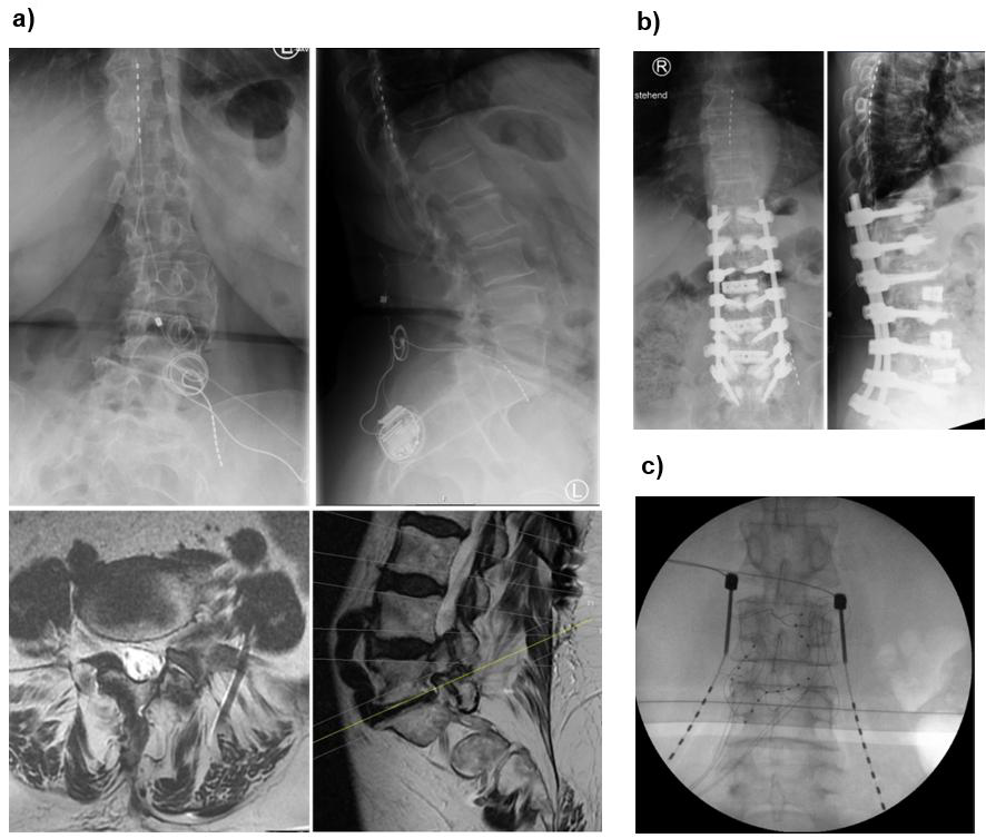
Figure 1. Representative cases demonstrating the suitability of Xtra4 in patients with complex anatomical or postoperative conditions. (a) Patient with residual foraminal stenosis after spinal surgery and progressive scoliosis, experiencing worsening leg pain unrelieved by conventional SCS. Revision in 2024 included placement of a new L5 lead on the left, combined with SCS. MRI shows foraminal stenosis in axial and sagittal views; axial image highlights the L5 lead in relation to the psoas muscle and nerve. (b) Patient with challenging postoperative anatomy and radicular pain in the left L3 region; a DRG lead was contraindicated due to prior surgery and scarring. (c) Patient referred with prior two DRG revisions, presenting with lead migration of DRG leads.
Results
Lumbosacral plexus anatomy and its variations
A precise understanding of the lumbosacral plexus is critical for effectively and safely applying the extraforaminal SNS technique. Due to these nerve structures’ deep location, anatomical complexity, and considerable inter-individual variability, anatomical understanding is necessary to optimize lead placement, maximize stimulation selectivity, and avoid complications.
General anatomy of the lumbar plexus (Figure 2): The lumbar plexus primarily comprises the ventral rami of spinal nerves L1 to L4, with occasional contributions from the T12 nerve root (via the subcostal nerve) [6]. It is located within the posterior compartment of the psoas major muscle, anterior to the transverse processes of the lumbar vertebrae [7]. The nerve branches typically emerge through or around the psoas major, making this region particularly important in planning the trajectory for lead implantation during Xtra4.
The major branches of the lumbar plexus include [7,8]:
- Iliohypogastric and ilioinguinal nerves (T12–L1): Emerge laterally and course over the iliac crest, innervating the lower abdominal wall and groin region.
- Genitofemoral nerve (L1–L2): Pierces the psoas major muscle and travels anteriorly; it has both genital and femoral branches.
- Lateral femoral cutaneous nerve (L2–L3): Passes across the iliacus muscle and beneath the inguinal ligament to supply the skin of the lateral thigh.
- Femoral nerve (L2–L4): The largest branch of the lumbar plexus, it exits laterally between the psoas and iliacus muscles, then enters the thigh beneath the inguinal ligament to innervate the quadriceps muscle group and provide sensory input to the anterior thigh and medial leg.
- Obturator nerve (L2–L4): Travels medially through the pelvis, exiting via the obturator foramen to supply the medial thigh muscles.
- Accessory obturator nerve (L3–L4, variable): In approximately 10%–30% of individuals, it may contribute to the innervation of the pectineus muscle.
Anatomical variations in branching patterns, trajectory, and fascial compartments [8–10] can affect access routes and the predictability of stimulation fields, reinforcing the importance of detailed intraoperative stimulation in each case.
General anatomy of the sacral plexus (Figure 2): The lumbosacral plexus is formed by the lumbar plexus (L1–L4) and the sacral plexus (L4–S4), interconnected via the lumbosacral trunk (L4–L5) [11]. The sacral portion of the plexus lies on the anterior surface of the piriformis muscle, deep within the pelvis, and contributes to the innervation of the lower extremities, pelvis, and perineum [8].
Key components of the lumbosacral plexus include [8]:
- Lumbosacral trunk (L4–L5): This structure descends into the pelvis and joins with sacral roots to form the sacral plexus.
- Sciatic nerve (L4–S3): The largest nerve in the body, it exits the pelvis via the greater sciatic foramen and provides motor and sensory innervation to most of the lower limb.
- Superior and inferior gluteal nerves (L4–S2 and L5–S2, respectively): These nerves innervate the gluteal muscles and are relevant in procedures targeting proximal lower limb neuropathic pain.
- Posterior femoral cutaneous nerve (S1–S3): Supplies posterior thigh and perineal region sensation.
- Pudendal nerve (S2–S4): Crucial for perineal motor and sensory function.
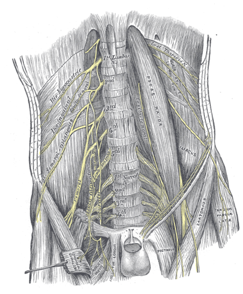
Figure 2. Anatomical illustration of the human lumbosacral plexus and iliopsoas complex. The figure highlights the spatial relationships between the nerves and surrounding anatomical structures, which are critical for accurate placement of extraforaminal spinal nerve stimulation leads in the lumbar region. Source: Gray, H. (1918). Gray's Anatomy: Descriptive and Surgical, 20th edition, Plate 823. Available at: https://upload.wikimedia.org/wikipedia/commons/7/7c/Gray823.png
The course of these nerves, particularly in relation to surrounding osseous landmarks and fasciae, is of great importance for accurate electrode positioning. Variations in the branching and exit points from the intervertebral foramina or pelvic spaces can affect stimulation success and may necessitate modification of the lead trajectory.
In the context of Xtra4, understanding these anatomical variations enables a patient-specific approach, enhancing targeted dermatomal coverage and reducing the risk of inadequate stimulation or patient discomfort (see Section “Anatomical variability and electrode trajectory”).
Anatomical considerations for lead placement: The nerve roots of the lumbosacral plexus exit the spinal canal via the intervertebral foramina, then course as spinal nerves laterally and anteriorly through the psoas muscle. Their orientation is generally oblique in the axial plane, with a downward-sloping trajectory from medial to lateral. This trajectory is crucial for accurate electrode alignment using the Xtra4 technique.
However, multiple factors can introduce variability [7,9,10,12]:
- Depth and angulation of the spinal nerve can differ depending on vertebral level and individual anatomy.
- At higher levels (L1–L2), the spinal nerve tends to lie more anterior and deeper, making access more difficult.
- The L4 and L5 spinal nerves often have a steeper and more posterior exit, sometimes lying closer to the dorsal elements, which may make them more amenable to extraforaminal targeting.
- Root bifurcation patterns, accessory branches, and anatomical anomalies (e.g., psoas hypertrophy, scoliosis, transitional vertebrae) can complicate electrode trajectory and limit stimulation response.
Clinical implications of anatomic variation: Due to anatomical variations, electrode positioning can be challenging and must be adapted to the specific course of each spinal nerve. In principle, advanced preoperative imaging, such as MRI or CT, is not strictly necessary but can help identify atypical anatomy. However, the most critical step is intraoperative stimulation.
Intraoperatively, careful attention should be paid to:
- Adjusting the trajectory and planning the optimal insertion angle based on motor response testing
- Controlling lead depth using lateral fluoroscopy
- Avoiding excessively medial or ventral advancement, which may bypass the intended nerve path
- The introduction of the electrode occurs smoothly and without resistance when the correct layer is reached, as the lead naturally follows the intended trajectory.
Additionally, some patients may benefit from cross-level stimulation, such as placing a lead through the L4 level to target the L5 spinal nerve, especially when the natural path of the nerves deviates from textbook descriptions (see Section “Segmental overlap and cross-level targeting”).
Anatomical and radiological considerations
Anatomical background: The lumbar and sacral spinal nerves emerge from the spinal canal through the intervertebral foramina and pass laterally through the paraspinal muscles before joining the lumbosacral plexus [13–15]. In the extraforaminal region—lateral to the pedicle—the spinal nerve is relatively superficial, located between the transverse processes and enveloped by connective tissue and small vessels.
This anatomical location is ideal for stimulation, offering mechanical stability and proximity to the dorsal sensory fibers. The DRG, located near the medial border of the foramen, is not the primary target of the Xtra4 technique. Instead, this technique aims to advance the lead along the spinal nerve within the extraforaminal space, targeting the nerve to the point where it contributes to plexus formation and gives rise to its branches.
A solid understanding of key bony landmarks—including the transverse process, the lateral margin of the facet joint, and the inferior aspect of the pedicle—is essential for safe and reproducible lead placement.
Imaging and visualization: Fluoroscopy (in both anteroposterior [AP] and lateral views) guides the needle and electrode into the extraforaminal space during surgery (Figure 3). Accurate visualization is critical to ensure safe and effective lead placement. Key radiographic features to confirm include:
- In the AP view: The lead tip should lie lateral to the lateral border of the pedicle, ideally positioned under or just medial to the midpoint of the transverse process. The lead body should course obliquely laterally, reflecting proper alignment with the spinal nerve (Figure 3a).
- In the lateral view: The lead should follow the anatomical course of the exiting spinal nerve and be positioned anterior to the posterior vertebral body line. A slightly oblique, inferolateral trajectory ventral to the vertebral body—except at L1 and L2—indicates engagement with the appropriate fascicular plane of the spinal nerve. At the L1 and L2 level, the lead often lies along or dorsal to the posterior vertebral body line (Figure 3b).
Fluoroscopy should be used throughout the procedure to confirm lead advancement, trajectory, and final positioning. We recommend capturing and storing high-quality final images in both AP and lateral views to document correct lead placement and provide a reference for future evaluation or revision, if necessary.
Surgical technique for lead placement
Required materials: For the Xtra4 approach, all available standard SCS/PNS implantable systems with 4- or 8-contact leads and an IPG can be utilized. In our cohort, we initially used 4-contact leads with extensions in cases requiring more than two leads. Later, this was replaced by four 8-contact leads connected to a 32-channel IPG to provide more stable stimulation coverage.
Leads with stiffer coatings are particularly suitable for this technique. Their increased rigidity offers greater mechanical stability in the extraforaminal space and helps reduce the risk of lead migration. The spacing between electrode contacts is not critical, as it is typical and desirable for multiple contacts to lie near the spinal nerve, enhancing the likelihood of effective and sustained neuromodulation.
Patient positioning and preparation: Similar to SCS implantation, the patient is positioned prone, with a mild abdominal cushion placed to reduce lumbar lordosis. Following antiseptic skin preparation and sterile draping, fluoroscopy is calibrated to obtain clear anteroposterior (AP) and lateral views of the target spinal level.
The procedure is typically performed under light sedation to ensure patient comfort while permitting intraoperative stimulation testing. However, since motor threshold stimulation (see Section “Motor threshold testing”) is prioritized for confirming accurate lead placement, the procedure may also be performed under general anesthesia when sedation is not feasible.
After sterile surgical field preparation, a local anesthetic is administered at the planned insertion site. Under fluoroscopic guidance, the entry point is identified at the inferomedial border of the transverse process of the target vertebra (Figure 3a).
Needle insertion and lead placement: A Tuohy needle is inserted at approximately a 90-degree angle or slightly shallower under fluoroscopic control until it contacts the lower bony border of the transverse process. The needle is then angled inferiorly and directed laterally, passing beneath the transverse process toward the extraforaminal space. Once the needle reaches this position, the stylet is then removed.
Advancement continues until a distinct “loss of resistance” is felt, indicating entry into the paravertebral space adjacent to the spinal nerve. This tactile feedback is similar to that experienced during a paravertebral block, yet distinct and unmistakable. In the lateral fluoroscopic view, the needle tip should lie beneath the pedicle and dorsal to the spinal foramen, ideally not crossing beyond the midline of the foramen (Figure 3b). Further advancement beyond this point is not recommended.
The electrode is then advanced through the needle in a smooth, craniocaudal direction along the connective tissue plane overlying the distal spinal nerve. If the electrode follows the correct anatomical plane, minimal manipulation is needed, as it advances naturally. If resistance is encountered, the lead should not be forced; gentle redirection or slight advancement may allow successful advancement. If this fails, the electrode should be withdrawn, and the needle bevel adjusted to a more lateral angle before reattempting placement.
Positioning the lead so that the proximal contact lies approximately 2–4 cm lateral to the foramen is typically sufficient and provides a safety margin against migration (Figure 3a).
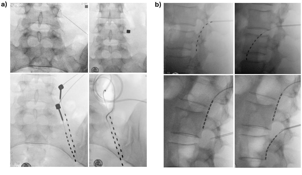
Figure 3. Radiographic placement of the extraforaminal lead. (a) Intraoperative fluoroscopy in anteroposterior (AP) view during implantation of Xtra4 electrodes at right L4 and L5. The entry point is marked medial to the midpoint of the transverse process. The needle is advanced to bone contact, with the lower images illustrating the optimal caudal and lateral needle angulation. The lead then courses obliquely laterally, indicating proper alignment with the spinal nerve. (b) Another case of Xtra4 implantation at left L1 and L2, lateral view. In the upper left image, the needle is introduced too early, meeting resistance and resulting in either no stimulation or activation limited to paraspinal muscles. In contrast, the upper right image shows correct placement, with the needle tip positioned dorsally up to the mid-pedicular line, and the needle advancing smoothly without resistance, enabling stimulation of the appropriate core muscles at low current. The lower images demonstrate L1 and L2 lead placement, where the lead often lies along or dorsal to the posterior vertebral body.
Intraoperative stimulation and electrode testing:
Motor threshold testing: Intraoperative stimulation is essential for confirming correct electrode positioning. Unlike paresthesia-based mapping, which depends on subjective patient feedback and may be unreliable under sedation, motor stimulation provides an objective, reproducible method for verifying lead alignment with the target spinal nerve.
Because spinal nerves are mixed nerves containing both motor and sensory fibers, low-frequency stimulation can reliably elicit visible muscle contractions when the electrode is appropriately positioned—often with very low stimulation amplitudes.
The standard stimulation protocol involves sequential bipolar stimulation across the contact array. We recommend beginning at the distal contact (tip of the lead), then testing central, and finally proximal contacts. This stepwise approach helps identify the electrode segments best aligned with the nerve and provides a useful topographical map for future programming.
Typical parameters for motor screening:
- Frequency: 2–10 Hz (commonly 4 Hz)
- Pulse width: up to 300 μs
- Amplitude: increased from 0.1 mA upward until a visible motor response (muscle twitch) is observed
Optimal placement is indicated by low-threshold, clearly visible contractions in the core muscles innervated by the targeted spinal nerve (e.g., quadriceps for L3–L4, tibialis anterior for L5, see Table 1). Ideally, consistent responses at lower current levels across multiple contacts suggest the lead is running parallel and close to the nerve (Figure 4).
The lower the current required to trigger a muscle response, the closer the electrode is likely positioned to the nerve. In optimal configurations, contractions are typically observed at less than 3 mA. Higher current requirements might sometimes be acceptable but may indicate suboptimal proximity to the nerve. While motor stimulation is generally well tolerated and not painful, increasing the amplitude enhances the strength of muscle contractions but does not cause discomfort; however, higher amplitudes are usually unnecessary.
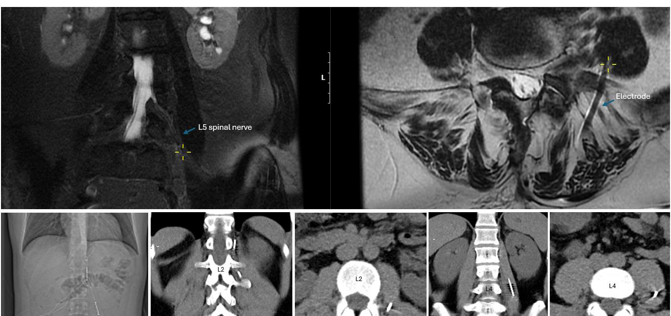
Figure 4. Upper panels: Coronal and axial MRI views demonstrating the proximity of the electrode to the left L5 spinal nerve within the psoas compartment in the scoliosis patient shown in Figure 1a. The yellow cross marks the electrode’s entry point into the psoas; the corresponding coronal image illustrates its parallel course and close proximity to the spinal nerve. Lower panels: CT images from another patient with groin pain after herniorrhaphy, implanted with an Xtra4 electrode at the level of L1 and L2 on the left side. The CT scans show the entry site and trajectory of the electrode along the L2 spinal nerve, with the last two images demonstrating its course within the psoas compartment. In both cases, imaging confirms accurate extraforaminal positioning relative to the targeted nerve structure.
|
Spinal Nerve |
Key Motor Muscles (Myotome) |
Sensory Area (Dermatome) |
|
L1 |
Internal obliques, transversus abdominis |
Groin, upper inner thigh |
|
L2 |
Iliopsoas |
Anterior thigh |
|
L3 |
Quadriceps femoris, adductors |
Distal anterior thigh, medial knee |
|
L4 |
Quadriceps, tibialis anterior |
Medial leg and ankle |
|
L5 |
Tibialis anterior, extensor hallucis longus, gluteus medius |
Lateral leg, dorsum of foot, great toe |
|
S1 |
Gastrocnemius, soleus, gluteus maximus |
Lateral foot, heel, sole |
Tonic stimulation: Once anatomical accuracy has been confirmed through motor screening, and if the patient is awake and cooperative, tonic stimulation may be applied to assess subjective coverage of the painful dermatome.
A typical testing setting involves
- Frequency: 20–80 Hz (commonly 40 Hz)
- Pulse width: up to 300 μs
- Amplitude: gradually increased in 0.1 mA increments until the patient perceives a paresthesia in the target area
It is important to note that pulse widths greater than 200 μs are rarely required, even during tonic stimulation. Increasing the pulse width beyond this threshold can sometimes lead to muscle cramping, stiffness, or an unpleasant pulling sensation in the groin area, which patients often describe as uncomfortable or bothersome.
If sensing responses occur at very low thresholds (e.g., <0.5 mA), we recommend gradually reducing the pulse width to 60 μs to enhance stimulation selectivity and provide a margin for future sub-threshold programming without inducing unwanted paresthesia during movement.
This two-phase approach—objective motor confirmation followed by subjective sensory mapping when possible—ensures accurate lead placement and optimal neuromodulatory coverage tailored to the patient’s pain distribution.
Anchoring technique
Once optimal positioning is confirmed, the Tuohy needle is removed, and the lead is secured to the fascia lumbodorsalis.
During the early phase of our experience—particularly in 2019 and 2020—the leads were not anchored, following the practice for DRG electrodes. Interestingly, during this period, lead migration occurred in 5 out of 38 patients (13%), yet most leads remained clinically effective despite displacement.
However, we observed a significant increase in migration rates with modern anchoring systems and techniques adapted from conventional SCS practice, where leads are routinely anchored to the fascia using an anchor. This was especially evident when the anchor tip was pushed through the fascia at a steep 90° angle: 33% in 2021, peaking at 67% in 2022, and remaining high at 37% in 2023. Although the exact rates varied among manufacturers, the issue was consistently observed regardless of the system or the implanting surgeon.
This phenomenon appears to be mechanically induced. The anchoring technique introduces tension vectors that pull the lead toward the skin, particularly when the fascia is tight or the anchor is misaligned with the lead’s natural trajectory. During revision procedures, it was noted that the leads were firmly attached to the anchors, and the anchors were securely fixed to the fascia, thus ruling out improper anchoring technique as the primary cause. In most cases, lateral fluoroscopy or postoperative X-rays revealed the formation of a loop beneath the fascia, indicating progressive extrusion of the electrode (Figure 5a).
Importantly, not all migrated leads required revision. In several cases, the leads remained sufficiently close to the spinal nerve to allow for successful reprogramming. In mild displacements, often involving only a few centimeters, clinical function could be restored by activating more distal contacts (Figure 5a, left).
Fine-tuning anchoring techniques to prevent device related complications: Lead migration remains one of the most significant complications when using the Xtra4 approach. Historically, up to 20% migration rates have been reported, leading to reduced therapeutic efficacy and the need for revision surgery (Figure 5a, right).
To systematically address this issue, we comprehensively analyzed technical factors related to lead fixation—particularly anchoring strategy, lead trajectory, fascial tension, and patient-specific anatomical characteristics associated with lead migration.
Our findings demonstrated that coated leads are generally more suitable, showing superior mechanical durability. No fractures were observed in coated leads, even under conditions of lead strain. In contrast, lead breakage occurred exclusively in uncoated or 4-contact leads.
Most migration cases were associated with anchoring techniques in which the anchor tip was inserted deep into the fascia, while the distal portion was superficially sutured. This configuration introduced tension vectors that, under the influence of muscle movement, gradually pulled the electrode toward the skin. In most cases, loop formation beneath the fascia was visible on lateral fluoroscopy or postoperative imaging (see Figure 5a). Importantly, no cases of distal migration were observed.
Based on these insights, we implemented two modified anchoring techniques (described below), which significantly enhanced lead stability. Since their introduction in 2024, 11 patients (26 leads) have been permanently implanted, and to date, no lead migrations have been observed.
These findings emphasize the critical importance of precise lead fixation and thorough intraoperative verification. A technically optimized anchoring strategy is vital in minimizing mechanical displacement and ensuring long-term therapeutic success in extraforaminal SNS using Xtra4 approach.
Technique 1: Perpendicular in-fascia anchoring using conventional anchors (Kugler approach): In this approach, a standard sleeve-type anchor (regardless of manufacturer) is inserted perpendicularly into the fascia, aligned with the trajectory of the electrode (Figure 5b). A small fascial incision is made at the needle entry site. The Tuohy needle is removed, the anchor is mounted onto the lead, and both are inserted into the fascial opening. The distal end of the anchor is sutured to secure the lead and then directly fixated to the fascia to prevent retrograde movement (see Figure 5b).
Advantages:
- Compatible with widely available standard anchoring materials
- Requires no modification of existing anchors
Limitations:
- For some systems, the anchor must be pre-mounted onto the lead before insertion, limiting the ability to confirm optimal neural placement before fixation. Post-anchoring confirmation of lead position using fluoroscopy is recommended. Repeating stimulation testing is advised to ensure clinical efficacy if the lead has shifted significantly from its intended location.
When injectable anchors are used, these limitations are largely mitigated. Injectable anchors can be deployed after optimal lead positioning, securing the lead within the fascia without requiring sutures. This allows for stimulation testing and lead adjustment before final fixation.
Technique 2: Extra-fascial anchoring with modified anchor (Kohr approach): This technique involves slightly modifying a conventional sleeve-type anchor, positioning it outside the fascia directly at the lead entry point. This configuration’s anchor is a mechanical stop to prevent retrograde lead movement (see Figure 5c).
The modification involves making a small longitudinal cut in the distal third of the anchor, allowing the electrode to exit through the midsection instead of the tip. The anchor is then securely sutured to the fascia and fixed at the lead entry point.
Advantages:
- The anchor remains superficial to the fascia, avoiding internal tension and potential fascial irritation
- If a lead revision is necessary, the anchor is easily accessible without the need for fascial dissection
Limitations:
- Standard anchors must be manually modified, as no commercial products are currently available for this configuration
- Care must be taken to ensure the modified anchor provides sufficient mechanical fixation and long-term stability
Both techniques have been successfully implemented without any lead migration or anchor-related complications. However, explantation has not yet been necessary in our series.
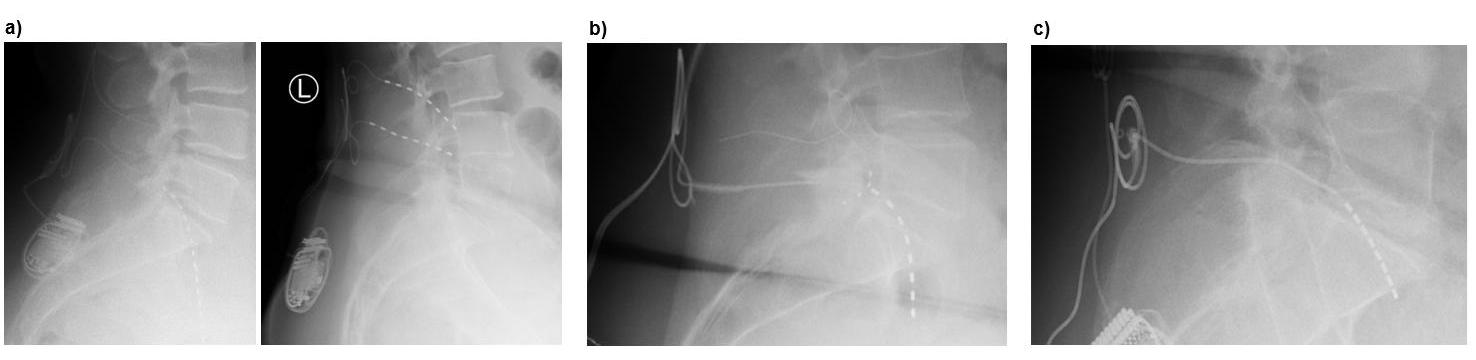
Figure 5. Lead migration and anchoring techniques. (a) Examples of lead migration: left image shows mild migration with formation of a subfascial loop (<1 cm), where reprogramming maintained effective stimulation; right image shows severe migration (>3 cm), in which reprogramming failed to restore coverage, necessitating surgical revision to correct the lead’s position on the nerve. (b) Perpendicular in-fascia anchoring using a conventional anchor (Kugler approach): a sleeve-type anchor is inserted perpendicularly into the fascia at the lead entry point and secured to both the lead and fascia, preventing retrograde migration. (c) Extra-fascial anchoring with modified anchor (Kohr approach): a conventional anchor is longitudinally cut so the lead exits through its midsection rather than the tip, then fixed outside the fascia at the lead entry site. The tip may be secured into the fascia or removed entirely. In both cases, only the lead—not the anchor—forms the 90° bend.
Challenges during lead implantation
Although the Xtra4 technique for extraforaminal SNS is generally straightforward when procedural steps are followed meticulously, anatomical variability—particularly in spinal nerves and plexus—can present significant challenges. Successful lead placement and reliable intraoperative stimulation require technical precision, understanding of individual neuroanatomy, and the flexibility to adapt intraoperatively. Table 2 summarizes the advantages, limitations, and key considerations of extraforaminal SNS.
|
Aspect |
Advantages |
Limitations |
|
Target specificity |
Reported to enable selective stimulation of the affected spinal nerve in the lumbosacral region beyond the intervertebral foramen, constituting a formal PNS approach for localized modulation of radicular pain |
Current evidence is limited to lumbar and lumbosacral applications; its feasibility and safety at thoracic or cervical levels remain undetermined. |
|
Analgesic efficacy |
Preliminary data suggest sustained pain relief in patients with focal neuropathic pain, particularly when conventional SCS or DRG-S is insufficient or not feasible. |
Limited effectiveness in cases involving widespread, multisegmental, or non-radicular pain syndromes. |
|
Procedural aspects |
Minimally invasive, avoids the epidural space and passage through the intervertebral foramen with their associated risks. Shallow learning curve. Cross-level targeting |
Requires procedural expertise, knowledge of lumbar/lumbosacral anatomy, intraoperative testing, and real-time imaging to ensure safe and accurate electrode placement. |
|
Safety profile |
Avoids epidural-related complications such as dural puncture, epidural fibrosis, or neural damage; generally associated with a low complication rate. |
Potential risks include direct nerve injury, local hematoma, infection, or transient neural irritation. |
|
Stimulation efficiency |
Placement in the nerve-adjacent region allows for lower stimulation thresholds, resulting in improved energy efficiency. Lower incidence of tolerance development. |
Stimulation amplitude and perception may vary with patient posture or movement, requiring adjustment of programming parameters. |
|
Applicability |
Particularly useful in patients with extensive epidural scarring following spinal surgery, or spinal hardware in place, where SCS or DRG-S lead placement is technically challenging. |
Post-surgical extraforaminal changes or anatomic variations may potentially make accurate lead placement more challenging in certain cases |
|
Patient experience |
Reported to provide focal analgesia, with improvement in function and patient satisfaction. |
Some patients may experience local discomfort or paresthesia associated with postural changes. |
|
Long-term outcomes |
Early clinical studies report sustained pain reduction, functional improvement, and decreased analgesic use over mid/long-term follow-up. |
Evidence remains limited; large-scale, multicenter, randomized controlled trials are needed to confirm both efficacy and safety. |
Anatomical variability and electrode trajectory: One of the most frequent challenges involves variations in the anatomical course of the spinal nerves, especially at levels L1–L3, but also at L4 and L5. Sometimes, the nerve may follow a flatter or more oblique trajectory, leading to misaligned needle orientation and suboptimal lead positioning if not recognized and corrected.
A prevalent issue is the absence of a motor response during intraoperative stimulation, despite seemingly correct fluoroscopic positioning of the electrode. This typically indicates that the lead is not in contact with the nerve due to an incorrect depth or misalignment with the nerve’s trajectory.
To address these challenges, we recommend the following technical strategies:
- Once the needle reaches the lower margin of the transverse process under fluoroscopy, it should be advanced laterally, maintaining a trajectory parallel to the spinal nerve. Medial redirection at this stage often results in bypassing the nerve entirely.
- If no satisfactory stimulation response is achieved, rotate the needle bevel to adjust the electrode’s exit angle. This small maneuver can significantly improve alignment with the nerve.
- In the lateral fluoroscopic view, optimal needle depth lies between the infrapedicular line (outer foramen border) and the mid-pedicular line. Due to increased risk of deep or ventral misplacement, more medial infrapedicular positions should be approached with caution and never with a stylet in place.
- Avoid excessively deep or ventral needle trajectories, as they may completely miss the spinal nerve and compromise efficacy and safety.
- If lead positioning appears correct but stimulation remains ineffective, adjust programming parameters first—particularly pulse width, which can be progressively increased within patient tolerance limits—before deciding to reposition or replace the lead.
Segmental overlap and cross-level targeting: Cross-level targeting can provide a viable and effective solution for successful lead placement in select cases - particularly in patients with altered anatomy, restricted access, or spinal hardware.
For example:
- The L5 spinal nerve can often be reached by entering at the L4 level, directing the lead caudally in a straight trajectory.
- Similarly, the L3 nerve root may be accessed via an L4 entry, angling the needle and lead more laterally, even across the iliac crest, depending on the curvature and course of the nerve.
- The L1 spinal nerve can often be reached by approaching from the T12 level (Figure 3b, lower right).
Understanding the exit angle and depth of the target nerve is essential, especially at levels where anatomical variation is common or fluoroscopic visualization is limited.
Spinal hardware and surgical history: Prior spine surgery and instrumentation can obscure anatomical landmarks—particularly the transverse process—on fluoroscopic imaging. However, basic anatomical knowledge remains helpful: spinal screws are anchored at the pedicles, providing a valid reference point for identifying adjacent structures.
In such cases, targeting laterally to the pedicle screw under fluoroscopy has proven to be a reliable method for accessing the spinal nerve, even when direct visualization is limited. This approach is efficient for patients with post-surgical radiculopathy and PSPS following spondylolysis, mainly when used in combination with an SCS lead for coverage of axial back pain.
Troubleshooting: stimulation failure and repositioning: If no motor response is observed despite seemingly correct anatomical lead placement, a systematic troubleshooting approach is recommended:
- Gradually withdraw the lead until the most proximal contact lies at the level of the foramen.
- Re-test stimulation across multiple contact points to check for delayed engagement or partial neural contact.
- If stimulation remains unsuccessful, remove the lead, redirect the needle bevel laterally, and reintroduce the lead along a slightly adjusted trajectory.
- Avoid forceful advancement if resistance is encountered; modify the insertion angle or depth under real-time fluoroscopic guidance.
These adjustments frequently resolve cases where the initial trajectory failed to achieve effective neuromodulation, helping to avoid full re-implantation.
In some cases, however, no workaround proves successful. When this occurs, complete withdrawal of the needle and restarting the procedure from a new puncture site is necessary. Starting fresh while carefully following the described implantation steps yields better results than repeated adjustments from a suboptimal trajectory.
Temporary trial and permanent implantation
During the percutaneous temporary trial phase, the lead was connected to a temporary external pulse generator. For permanent implantation the final entry point is positioned slightly more cranially—at the midpoint of the transverse process—to allow for a shallower insertion angle. Once the lead is placed and confirmed as before, the needle is withdrawn and secured to the fascia (See Section “Anchoring technique”). Strain-relief loops are created, and the leads are tunneled subcutaneously to the implant site in the buttock, connected to a conventional SCS IPG.
Programming
During trial: Programming during the trial phase is straightforward and typically involves setting a bipolar configuration to achieve the best motor and sensory responses. Frequencies between 20 Hz and 40 Hz are preferred, with pulse widths usually kept below 200 µs. Pulse widths exceeding 200 µs are rarely necessary and often cause discomfort. At lower current amplitudes, pulse width and frequency adjustments may be required to optimize efficacy.
Coverage of the targeted area must be precise to expect a clinical effect. The therapeutic effect usually manifests relatively quickly, often within one to two days. However, the trial phase at our center typically lasts around seven days, as required by our health insurance providers. We frequently observe significant improvement much earlier in the trial.
Notably, improvements in physical function often exceed pain reduction and tend to occur rapidly during the trial phase.
After permanent implantation: Post-permanent implantation programming closely follows the principles established during the trial phase. Some patients experience discomfort from paresthesia during the trial, leading to the adoption of high-frequency stimulation parameters, typically above 80 Hz but not exceeding 300 Hz, to mitigate this issue.
Additionally, modern waveform modalities have been tested with varying degrees of success. For example, in some cases, burst stimulation and fast-acting subperception therapy (FAST) waveforms have shown efficacy. The authors believe that active recharging plays a crucial role in the effectiveness of FAST stimulation.
Moreover, programming adaptive stimulation has supported many patients, particularly improving mobility. Conversely, cyclic stimulation settings were ineffective in our cohort and were generally perceived as unpleasant due to the noticeable sensation when the current cycles are on and off.
Patients have also benefited from feedback mechanisms such as closed-loop stimulation. Results related to these approaches will be presented in a forthcoming case series.
Discussion
The Xtra4 technique for extraforaminal SNS of the lumbar spinal nerves represents an innovative and promising advancement in neuromodulation. By precisely targeting the extraforaminal course of the spinal nerves, this approach enables focused stimulation with adequate coverage of the painful dermatome as a formal PNS technique, without involving stimulation of the DRG. This addresses several limitations of conventional methods and provides a valuable alternative when standard neuromodulation therapies are contraindicated or ineffective.
The anatomical and radiological landmarks described in this study offer a reproducible and safe framework for electrode implantation for clinicians seeking to adopt this technique. Precise alignment with bony landmarks and continuous fluoroscopic guidance during the procedure are essential for success. Equally important is a thorough understanding of spinal nerve anatomy, surrounding structures, potential anatomical variations, and associated challenges [7–11]. Intraoperative motor threshold testing has proven essential, offering an objective means to confirm optimal electrode placement, which can complement or even replace subjective patient feedback, particularly in sedated or anesthetized patients.
Lead stability was markedly enhanced using coated 8-contact leads combined with optimized anchoring techniques. Despite secure superficial fixation, initial use of conventional anchoring methods surprisingly resulted in high rates of lead migration, likely due to unfavorable tension vectors and fascial strain. The introduction of two modified anchoring methods effectively eliminated this issue, with no migrations observed since their implementation in 2024. These findings highlight the critical importance of anatomically adapted and precise fixation to ensure long-term lead stability and therapeutic success.
The challenges posed by anatomical variability, prior spinal surgeries, and the occasional necessity and the unique opportunity for cross-level targeting highlight the need for procedural flexibility—even within standardized protocols. In such cases, reliable intraoperative motor threshold testing remains indispensable. The technical recommendations presented in this paper for adjusting needle and lead trajectories, combined with motor stimulation, enable individualized procedural optimization, likely contributing to higher success rates and improved patient outcomes.
Regarding programming, combining intraoperative motor and tonic stimulation to confirm optimal lead positioning, followed by adequate sensory coverage during the trial phase, led to rapid and sustained pain relief and significant functional improvements. Emerging stimulation modalities—high-frequency, FAST, burst, and modern technological advancements such as adaptive and closed-loop stimulation—have shown promise in our experience. However, further clinical studies will be needed to confirm their efficacy and refine parameter selection.
This technique primarily shares indications with DRG stimulation but offers distinct advantages [3]. It requires no additional specialized hardware and is compatible with any standard implantable SCS/PNS system, making it especially useful in countries where DRG stimulation is not approved. The learning curve is very shallow due to its simplicity and straightforward implantation, without incurring higher costs than a conventional SCS procedure, which may facilitate broader clinical adoption.
Essentially, this method functions as a PNS. In Europe, most SCS systems are approved for PNS, whereas such approvals are less common in the USA. Instead, the US market offers other PNS systems with cylindrical leads for percutaneous use and implantable IPGs resembling SCS systems.
We recommend starting with this technique as a rescue option when alternative treatments are unavailable. Two centers—one in Argentine Republic and one in the Czech Republic—have initiated and performed the first implantations successfully. This paper is based on numerous inquiries from colleagues interested in adopting this method but remain uncertain about various aspects. Once initiated, the procedure can be implemented relatively quickly as a primary option due to its simplicity and straightforward nature.
Moreover, MRI conditionality remains a concern: most newer SCS systems are MRI-conditional when leads are implanted epidurally, but once implanted in the peripheral nerve region, this use is off-label and lacks formal approval. In one of our patients, an MRI was performed for a new onset of pain at a different spinal level, suspected to be a disc herniation. Imaging demonstrated the proximity of the lead to the L5 nerve (Figure 4). Following conservative therapy, the patient’s pain improved, and the stimulation continued to provide the desired analgesic effect with very low current for effective stimulation at the L5 level.
Our previous work reported that four patients had to undergo explantation due to the lack of MRI compatibility [4]. It is hoped that broader adoption of this method will encourage manufacturers to pursue MRI labeling, so patients benefiting from this therapy are not left without options due to imaging limitations.
Another limitation of this study is the lack of comprehensive long-term data on the reliability of the modified anchoring techniques. Although broader implementation across additional centers has begun, prospective multicenter trials will be essential to validate these approaches' generalizability and clinical utility.
This highlights the significance of providing a detailed description of the technique and its adaptability, emphasizing the value of this publication in promoting a consistent and safe procedural standard—drawn from our extensive experience with over 300 implanted leads to date. Despite these encouraging results, current evidence remains limited, and comprehensive long-term, multicenter data are lacking. Future studies should prioritize large-scale trials and mechanistic investigations to refine stimulation parameters and further elucidate the neurophysiological basis of extraforaminal SNS. Such efforts will be essential to guide broader clinical implementation and optimize patient outcomes.
Conclusion
This technique for extraforaminal SNS represents a valuable addition to the neuromodulation toolkit. It offers a safe, effective, minimally invasive, and versatile method of targeted PNS, especially in clinical scenarios where conventional neuromodulation options are not viable or contraindicated. As such, it holds significant potential to improve outcomes and quality of life in patients suffering from chronic neuropathic pain. Further research is warranted to establish long-term efficacy, safety, and cost-effectiveness, and to optimize stimulation parameters for broader clinical adoption.
Acknowledgment
We would like to thank our colleague Pablo Graff (Buenos Aires, Argentine Republic) for providing valuable comments, following his first successful implantation of the extraforaminal spinal nerve stimulation, using this XTRA4 method.
Authorship Statements
Danielle Kohr: Conceptualization; Investigation; Project administration; Writing – original draft, review & editing; Methodology. Alaa Abd-Elsayed: Conceptualization; Writing – review & editing; Methodology. Sudhir Diwan: Conceptualization; Writing – review & editing. Visualization. Dr. Kugler: Conceptualization; Supervision; Investigation; Writing – review & editing.
Source(s) of Financial Support
This research received no specific grant from public, commercial, or not-for-profit funding agencies.
Conflict of Interest
Dr. Kohr, Dr. Abd-Elsayed, and Dr. Diwan have no relevant conflicts of interest related to this work. Dr. Kugler is the registered owner of the trademark Name Xtra4.
References
2. Mekhail N, Deer TR, Kramer J, Poree L, Amirdelfan K, Grigsby E, et al. Paresthesia-Free Dorsal Root Ganglion Stimulation: An ACCURATE Study Sub-Analysis. Neuromodulation. 2020 Feb;23(2):185–95.
3. D'Souza RS, Kubrova E, Her YF, Barman RA, Smith BJ, Alvarez GM, et al. Dorsal Root Ganglion Stimulation for Lower Extremity Neuropathic Pain Syndromes: An Evidence-Based Literature Review. Adv Ther. 2022 Oct;39(10):4440–73.
4. Kohr D, Abd-Elsayed A, Kugler M. Extraforaminal Spinal Nerve Stimulation for Neuropathic Pain: Description of the New Approach, Safety, and Long-term Efficacy. Neuromodulation. 2025 May 16:S1094-7159(25)00147–3.
5. Kohr D, Diwan S, Kugler M. Long-Term Efficacy of a Novel Extraforaminal Approach for Nerve Root Stimulation in Complex Regional Pain Syndrome: A Case Report. Pain Med Case Rep. 2024 Jul;8(5):167–71.
6. Tubbs RI, Gabel B, Jeyamohan S, Moisi M, Chapman JR, Hanscom RD, et al. Relationship of the lumbar plexus branches to the lumbar spine: anatomical study with application to lateral approaches. Spine J. 2017 Jul;17(7):1012–6.
7. Gandhi KR, Joshi SD, Joshi SS, Siddiqui AU, Jalaj AV. Lumbar plexus and its variations. Journal of the Anatomical Society of India. 2013 Jun 1;62(1):47–51.
8. Neufeld EA, Shen PY, Nidecker AE, Runner G, Bateni C, Tse G, et al. MR imaging of the lumbosacral plexus: a review of techniques and pathologies. Journal of Neuroimaging. 2015 Sep;25(5):691–703.
9. Nontasaen P, Das S, Nisung C, Sinthubua A, Mahakkanukrauh P. A cadaveric study of the anatomical variations of the lumbar plexus with clinical implications. Journal of the Anatomical Society of India. 2016 Jun 1;65(1):24–8.
10. Farny J, Drolet P, Girard M. Anatomy of the posterior approach to the lumbar plexus block. Canadian Journal of Anaesthesia. 1994 Jun;41(6):480–5.
11. Tubbs RS, Iwanaga J, editors. Surgical anatomy of the sacral plexus and its branches. Elsevier Health Sciences; 2020 May 11. pp. 1–3.
12. Anloague PA, Huijbregts P. Anatomical variations of the lumbar plexus: a descriptive anatomy study with proposed clinical implications. Journal of Manual & Manipulative Therapy. 2009 Dec 1;17(4):107E–14E.
13. Davis TT, Bae HW, Mok JM, Rasouli A, Delamarter RB. Lumbar plexus anatomy within the psoas muscle: implications for the transpsoas lateral approach to the L4-L5 disc. J Bone Joint Surg Am. 2011 Aug 17;93(16):1482–7.
14. Di Benedetto P, Pinto G, Arcioni R, De Blasi RA, Sorrentino L, Rossifragola I, et al. Anatomy and imaging of lumbar plexus. Minerva Anestesiologica. 2005 Sep 1;71(9):549.
15. Jengojan S, Schellen C, Bodner G, Kasprian G. Bildgebung des Plexus lumbosacralis : Diagnostik und Therapieplanung mithilfe hochaufgelöster Verfahren [Imaging of the lumbosacral plexus : Diagnostics and treatment planning with high-resolution procedures]. Radiologe. 2017 Mar;57(3):195–203.