Abstract
Loss of mobility and independence directly affects the quality of life of many vulnerable individuals. In order to address this, researchers have been developing wearable walking assist exoskeletons to aid users with their daily activities. While this technology has advanced tremendously in the past decade, current exoskeletons are yet to be ergonomic, causing discomfort and injuries to the user, leading to early device rejection. This research intends to assess the kinematic and kinetic compatibility of a novel knee joint suitable for exoskeletons. The proposed knee design can be adapted to accommodate a kinematic offset and optimize force delivery. This is achieved by ensuring that the mechanical and biological joint rotation axes are aligned and that the moment arm can be varied to mimic the mechanical characteristics of a biological knee. Model simulations and mechanical testing of fabricated prototypes were achieved to analyze and validate the design. Results confirmed the compatibility of the design, which demonstrated kinematic absolute error values of 1.68 and 0.32 mm for the offset and aligned joints, respectively. It was shown that the moment arm can be varied throughout flexion, allowing future iterations to achieve optimal and effective moment transfer.
Keywords
Assistive devices, Brace, Exoskeleton, Gerontechnology, Knee, Polycentric, User interfaces
Introduction
As the number of elderly, vulnerable, and disabled individuals is expected to grow in the future, the need for walking assistance is anticipated to increase accordingly. More specifically, muscle weakness around the knee joint can render mobility difficult. Thus, sustaining daily physical activity can be challenging or even impossible. In order to preserve the independence of vulnerable individuals, walking assist exoskeletons (WAEs) must be well adopted and accepted into their daily lives. This will require further improvement in device ergonomics, among other factors, such as ease of use. Ergonomics and comfort are key points to be considered when attempting to improve the user acceptance rate of assistive devices.
While exoskeleton technologies have recently progressed significantly, their mechanical designs do not adequately consider the complexity of human joint articulations; most importantly, the knee plays a significant role in human mobility. The knee joint is a critical and robust joint that transfers significant loads in three-dimensional space. While the joint allows six degrees of freedom (DOFs), bony and ligamentous structures constrain the translations of the joint in the frontal and transverse planes [1]. On the other hand, there are significant anterior-posterior translations in the sagittal plane. Due to this, the knee joint has an instantaneous center of rotation (ICR) and undergoes polycentric motion [2]. Researchers have analyzed and developed models to represent the ICR translation of the average knee [3-7]. Walker et al. proposed one of the most comprehensive models of the ICR, which serves as a basis for modelling in this study.
Since the migration of the ICR is often neglected during exoskeleton joint design, a mismatch is created. The mismatch between the DOFs of the two joints causes offsets between the rotation axes, which in turn creates undesirable residual forces [8,9]. Offsets and misalignments can influence the user's voluntary range of motion (ROM), natural patterns of movement, and muscle activation patterns, and can increase metabolic cost [2,10]. It also tends to interfere with the transfer of assistive torques onto the body, cause discomfort or pain, and even lead to long-term injury. Hence, offset must be avoided.
Several commercially available powered WAEs use single-axis joints that are ergonomically insufficient for daily wear and are susceptible to user rejection. The Keeogo+ [11], HAL for Well-Being Lower Limb Type Pro [12], and Indego Personal [13] are all examples of devices with single-axis joints. Since these joints rotate about a single point, any offset between the ICR of the device and the biological knee is compensated by compression of soft tissues or strapping slip. Consequently, this restricts the natural motion of the user, causes discomfort, reduces the device's efficiency, and can lead to early user rejection. One promising solution is the integration of polycentric knee articulation.
Since the field of orthotics research is more mature than that of WAEs, there has been more success in improving the ergonomic and kinematic compatibility of orthoses. The double-hinge gear joint is a knee orthosis designed to mimic the biological knee better than a single-axis joint [14]. This orthosis comprises two single-axis hinge joints with meshing gear teeth to ensure they rotate at the same rate. Another type of polycentric joint was designed by Walker et al. based on their modelling of the ICR of the biological knee. Using a pin on the femoral component that fits into a slot on the tibial component combined with a cam, this joint effectively follows a pre-defined path of ICR [7]. The shape of the cam was optimized to provide the correct amount of translation at a given knee flexion angle. An axial pin allows for internal-external rotation of the tibial component, allowing this device to align itself in the transverse plane passively.
Researchers have begun implementing polycentric exoskeleton knee joint designs [15]. The iT-Knee [16], Self-adjusting, Isostatic Exoskeleton [17], HUMA [18], Anthro-X [19], AssistOn-Knee [20], S-Assist [21], and Adaptive Coupling Joint [22] are all examples of existing devices with polycentric knee joints. Though these designs consider the complexity of the biological knee, they suffer drawbacks in the form of bulkiness and heaviness.
WAEs present an additional challenge compared to orthoses for knee joint design; effective force transfer is critical in these systems. In the biological knee, the patella provides a variable moment arm for force transfer. The physical structure of the patellar mechanism creates an inverse relationship between the moment arm and the degree of knee flexion; the patella provides a large moment arm at low knee flexion and a small moment arm at high knee flexion [23]. These kinematic and kinetic characteristics, provided by the patellar mechanism, are, therefore, important inspiration factors in WAE knee joint design. In taking inspiration from orthoses and the biological knee structure, the ergonomics of WAEs could be improved while allowing for efficient force transfer. This study proposes a knee joint suitable for WAEs that improves ergonomics by optimizing kinematic compatibility between the user and the device and optimizes the actuation system by achieving a variable moment arm to the knee joint.
Materials and Methods
Model
For this study, motions outside the sagittal plane are neglected; thus, the model proposed by Walker et al. was simplified to a 2-dimensional system to represent the average biological knee (Figure 1). This model predicts the intersection of the transverse axis with the sagittal plane, meaning that the translation of the midpoint between the medial and lateral femoral condyles is in the sagittal plane. The origin point is identified as the point of the ICR at 0° flexion. Equations (1) and (2) represent the average translation of the ICR, where x1 is the translation in the anterior-posterior direction in mm, y1 is the translation in the proximal-distal direction in mm, and θ is the knee flexion in degrees.
x1= −0.0602 θ + 0.0000178 θ2 (1)
y1 = −0.05125 θ + 0.000308 θ2 (2)
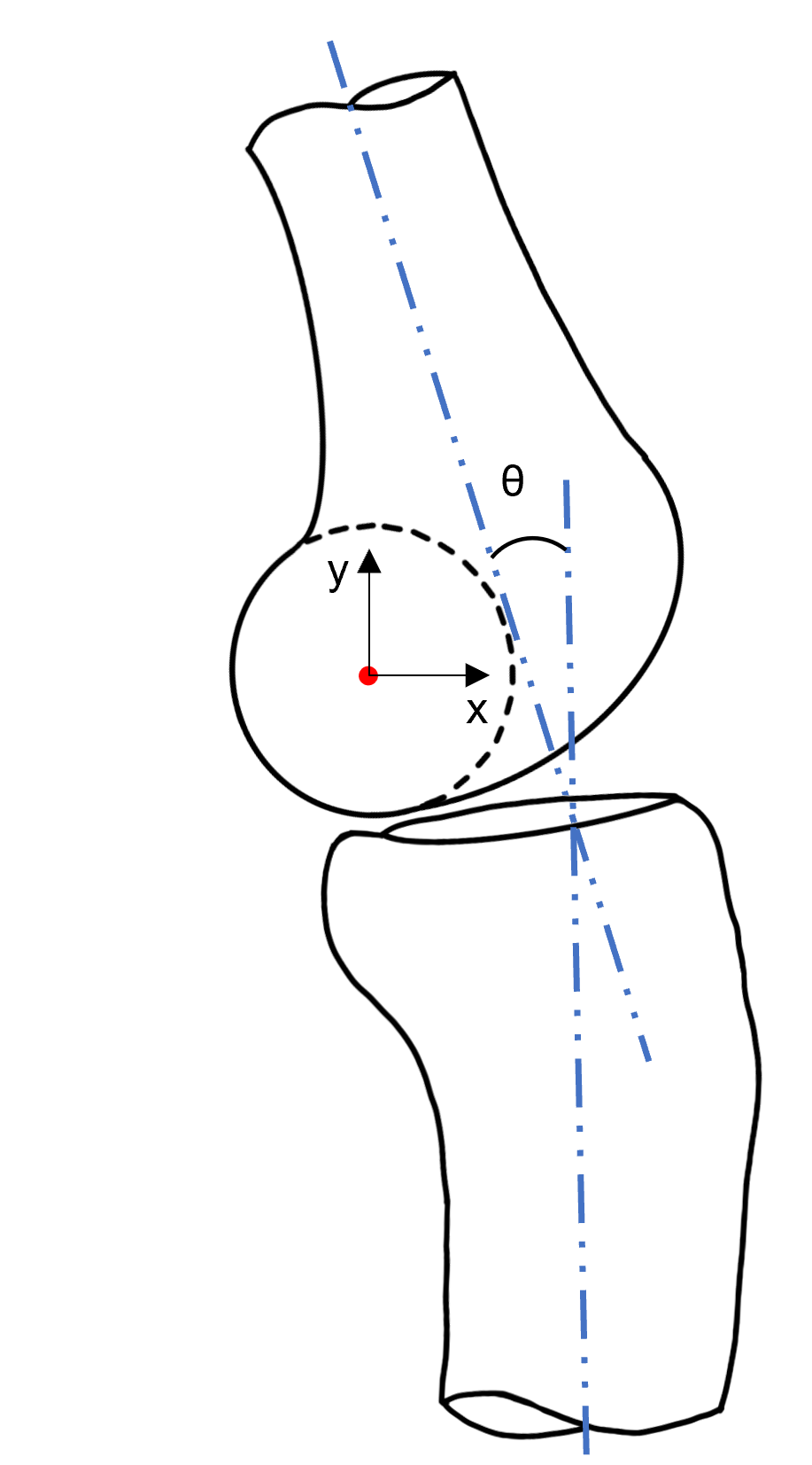
Figure 1. ICR model adapted from the model developed by Walker et al. Flexion angle (θ) is defined as the angle between the long axes of the femur and tibia (blue). The ICR is indicated by a red point at the midpoint between the center of the femoral condyles.
Pre-design analysis
To understand the shortfalls of single-axis and double-hinge gear joints, their ICRs were compared to the biological knee. Using MATLAB, each design was simulated through a range of flexion (0° to 120°), and their kinematic paths were compared to the modified ICR model developed by Walker et al. (Figure 2). The double-hinge gear joint was simulated at various radii: 2, 4.5, and 7 mm. One can prioritize matching the displacement of the biological ICR in the x- or y-axis by changing the radius of the gears. Gears with a radius of 2 mm may be complicated to manufacture and do not achieve enough x-axis translation. Similarly, the 7 mm gears significantly overshoot the y-axis displacement (by approximately 5 mm). A compromise is achieved if one sets the radius to a value in the middle of the two, 4.5 mm. This is an improvement over the 2 and 7 mm gears, but a significant difference persists between the ICR translation paths. An ideal joint with a pre-defined path of ICR would have a trajectory identical to the biological knee.
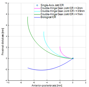
Figure 2. ICR comparison of the biological knee, single-axis joints, and double-hinge gear joints with radii of 2, 4.5, and 7 mm. The center of rotation for a single-axis joint is fixed and represented by a single point.
The impact of ICR misalignment for each joint was also evaluated. A simulation in MATLAB was generated to visually compare the offset between a single-axis joint, a double-hinge gear joint with a radius of 4.5 mm, and the average biological knee (Figure 3). In all cases, a point at the location of typical shank cuffs was selected at x = 10 mm and y = -70 mm, where the origin is located at the ICR at 0° flexion. These points were subjected to a rotation of 120° about the biological ICR, and a curve was drawn for each joint. The single-axis joint provides a circular path, whereas the biological knee translates throughout flexion. The offset increases as a function of flexion angle, which would lead to harmful discomfort to the user. Typical cuff positioning in WAEs can create an offset of approximately 7 mm at 120° flexion. Therefore, it can be stated that single-axis joints provide poor alignment with the biological knee center and should not be used in powered WAEs, especially when the device transmits considerable force. Visibly, the double-hinge gear joint (at 4.5 mm gear radius) has smaller offset magnitudes than the single-axis joint. Though it is an improvement, this design remains insufficient to match the kinematics of the biological knee.
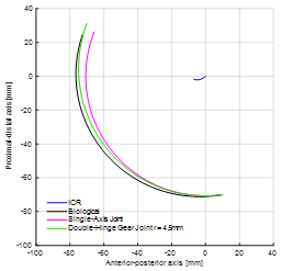
Figure 3. Simulation of the offset between the biological, single-axis, and double-hinge gear joints. A point at a common location of cuffs (x = 10 mm and y = -70 mm) is tracked throughout flexion for each joint type.
Design criteria
The goal of improving the ergonomics of WAE knee joints requires researchers to consider necessary elements of design carefully. From a kinematic perspective, the joint must be polycentric to emulate the motion of the natural knee; however, it must also transfer force reliably and assist the actuation system with optimal force delivery. Inspired by the patellar mechanism, the aim is to have a resulting knee joint design with varying moment arm throughout flexion. The design should also be modular and adaptable in order to be positioned at different locations that include offset configurations. There are instances where one may be unable to align the mechanical knee joint with the biological joint (e.g. size restrictions, mechanical constraints). In this case, an alternative shape could permit the rolling and sliding motion of the knee.
Based on the above, design criteria were proposed. These criteria include the ability to transfer force from an actuator, vary the moment arm throughout flexion, accommodate offsets of the knee joint in the sagittal plane, and prevent hyperextension knee injuries. Table 1 provides the established design criteria.
|
# |
Design Criterion Description |
|
1 |
The joint must be polycentric and follow the ICR path. |
|
2 |
The joint must be able to transfer force reliably. |
|
3 |
The joint must be able to vary the moment arm throughout flexion. |
|
4 |
The joint must accommodate offsets of the biological knee joint in the sagittal plane. |
|
5 |
The ROM of the joint must be 0° to 120° flexion. |
|
6 |
Physical restrictions must be implemented to avoid hyperextension knee injuries. |
|
7 |
The design must allow actuator placement proximal to the knee to reduce inertia and felt weight. |
Design concept
The design implemented in this study was inspired by the orthosis presented by Walker et al. A pin-in-slot mechanism provides polycentric rotation; the femoral component has slots, and the pins are fixed to the tibial component (Figure 4). Distinctively, three pins are implemented in the design. One of the pins is aligned with the ICR, allowing for kinematic compatibility with the biological knee. A second pin ensures that the first pin moves along its path at the appropriate rate, and the third pin provides extra stability, ensuring only one kinematic solution. At the limit of the ROM, pin motion is restricted by the end of the slots; this prevents hyperflexion and hyperextension.
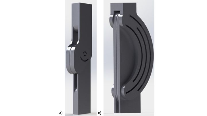
Figure 4. SolidWorks renderings of the joint design concept: A) aligned joint, B) offset joint. A tibial component with pins is shown connected to the femoral component with slots. Eyelets and cables are omitted for clarity.
Actuation is provided using a cable and pulley system to allow for flexibility in actuator placement. This allows the actuator to be placed nearer to the user's center of mass, reducing felt weight and energy expenditure [24]. The cable is routed from the posterior side of the femoral component around a pulley on the tibial component and back up the anterior side of the femoral component. Tension is applied to the posterior and anterior ends of the cable to flex and extend the joint, respectively. The moment arm is measured from the pulley's outer edge to the ICR of the device. To achieve moment arm variation, the profile of the pulley is noncircular. Pulley shapes were designed based on a geometrical angle measurement from 0° to 120° in increments of 15° using reference biological moment arms from [25].
This novel design concept can accommodate an offset in the sagittal plane by selecting appropriate alternate pin-in-slot pathways. Given a prescribed offset distance, a joint that remains compatible with the ICR of the biological knee can be created. For this study, two joints were evaluated: one in an aligned configuration and one with an offset.
Prototyping and fabrication
Experimental prototypes were created using the Ultimaker 3 Extended 3D Printer using polylactic acid material at a 0.2 mm profile and with 10% infill. The femoral components were printed in two parts for assembly, and the tibial components were printed in a single piece. Steel pins were inserted into both prototypes' tibial components and affixed with cyanoacrylate (CA). Due to its minimal strain and low cost, twisted polypropylene mason twine with a diameter of 2 mm was used for cables. A bright orange coloured cable was a clear choice for high visibility against the black PLA material. The cable was fixed to the tibial component with aluminum wire and CA. Eyelets were fixed to the femoral component with CA as cable guides.
Experimental testing
Two testing platforms were developed to validate that the proposed design satisfies the established criteria. The first testing platform (Figure 5) was designed to rotate the knee joint in the sagittal plane at 15° intervals from 0° to 120° flexion, capturing images at each instance. This permitted the evaluation of their kinematics and moment arm performance. Two U-shaped supports at the proximal and distal ends of the joints were fixed to a plywood platform by tightening nuts and bolts through two curved tracks that allow flexion and extension. The cable was pulled taut and fastened at every 15° interval.
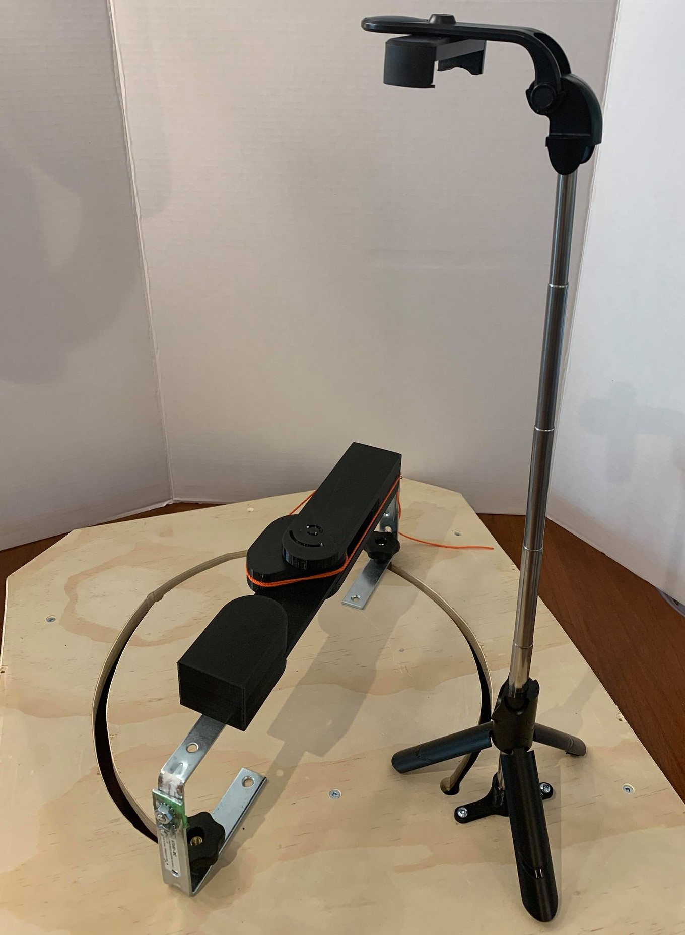
Figure 5. First testing platform. Prototypes are fixed to a board with two curved tracks by adjustable U-shaped supports. A tripod is fixed to the board to take photos of the prototypes at prescribed intervals of 15°.
A tripod was fixed to the platform to ensure that images were taken from the same reference point, and a wireless remote was used to initiate image capture at a distance. The femoral component of the joint was fixed at the end of its track and did not move throughout testing. A 12-inch goniometer was applied to measure the flexion angle before each trial and was removed before image capture.
MATLAB software was then used to normalize the rotation, origin, and scale of all images before identifying the location of pins and the last visible points of contact between the pulley and the cable using the data cursor feature. Experimental pin locations were plotted against their theoretical paths to evaluate the accuracy of the joint in reproducing the biological knee model. To analyze moment arm variation, digital measurements were taken from the ICR to the last point of contact between the pulley and the cable. The absolute error was evaluated for each data point to quantify the agreement between simulations and experimental results.
A second experimental setup (Figure 6) was developed to validate that the joints possess a single kinematic solution. The femoral components were fixed to a plywood board, and markers were attached to the distal ends of the joints. Cables were pulled manually to generate ten cycles of full ROM flexion/extension in each joint, and the resulting curves were visually inspected.
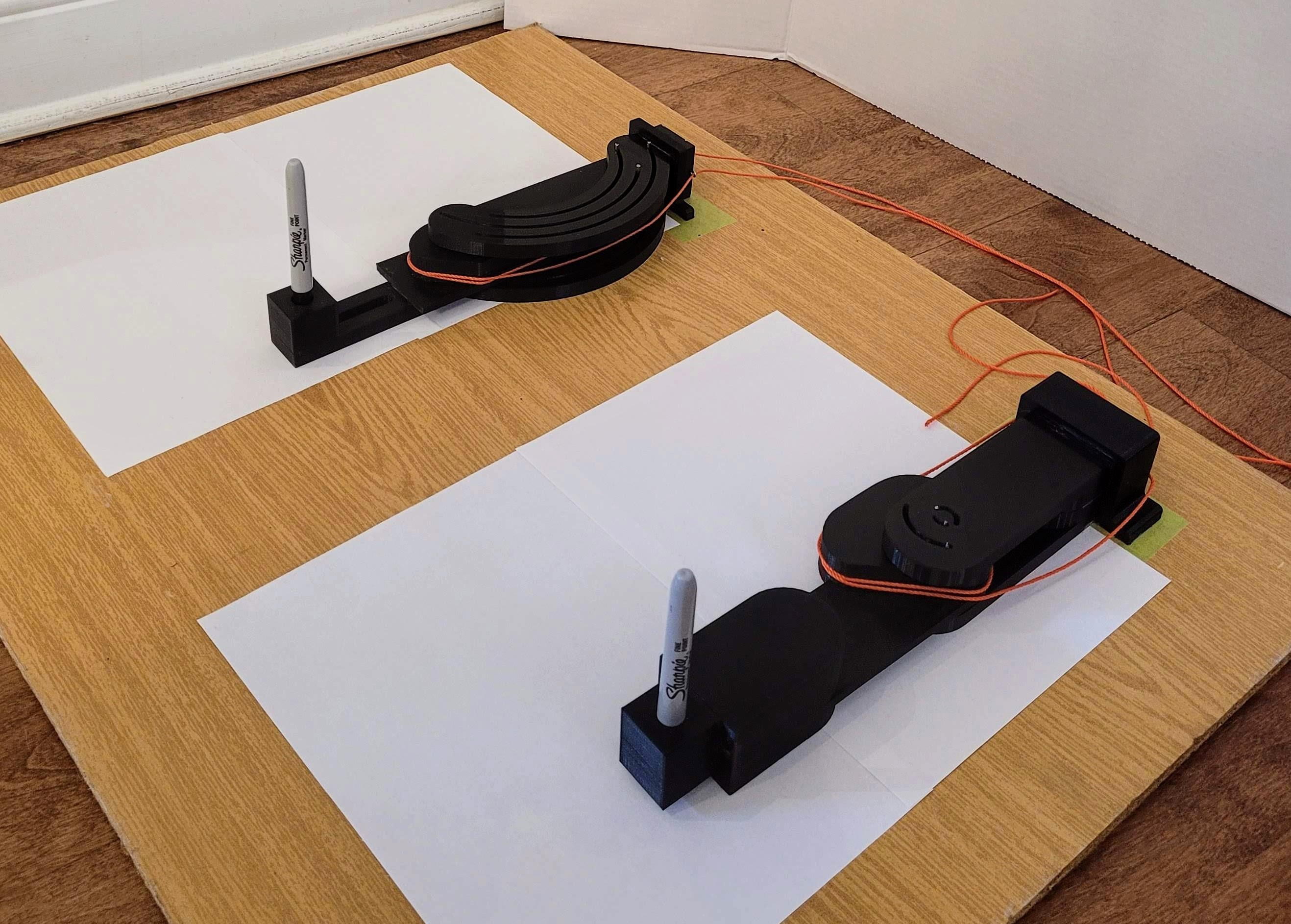
Figure 6. Second testing platform. The femoral components of each prototype are fixed to a board. Markers are affixed to the distal ends of the tibial components so that when tension is applied to the cables, curves are drawn.
Results
The results obtained are shown in Figures 7-10. The kinematic absolute error results for both prototypes can be found in Table 2. On average, pins 1, 2, and 3 of the aligned joint had 0.37, 0.36, and 0.22 mm errors, respectively. The offset joint had average errors of 1.71, 1.68, and 1.64 mm. Across all pins, the average kinematic absolute error for the aligned and offset joints were 0.32 and 1.68 mm, respectively.
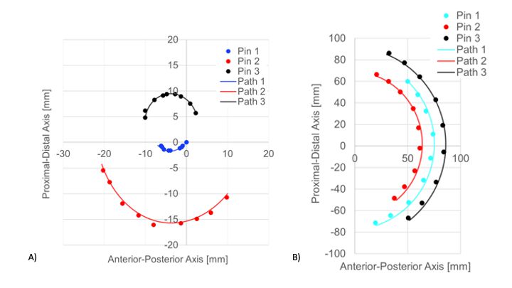
Figure 7. Kinematic experimental results for the A) aligned and B) offset joints. Locations of pins are represented by points overlaid on simulated paths.
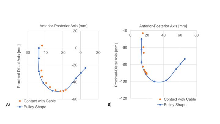
Figure 8. Cable contact experimental results for the A) aligned and B) offset joints. Pulley shape data points are plotted for every 15° interval from 0° to 120°.
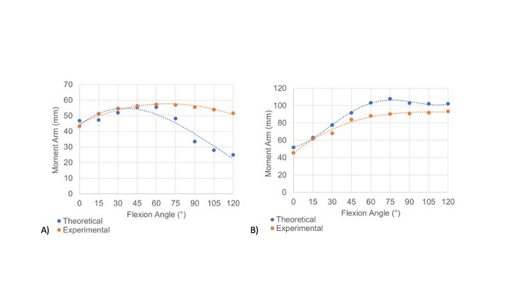
Figure 9. Moment arm experimental results for the A) aligned and B) offset joints. The aligned joint had an average moment arm error value of 34.33%, and the offset joint had an average error value of 10.65%.
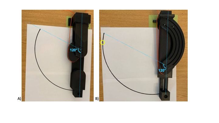
Figure 10. Experimental results from the second testing platform for A) aligned and B) offset joints. Markers were removed for clarity. The maximum ROM is indicated in light blue, and a small imperfection in the drawn curve is circled in yellow.
|
|
Absolute error (mm) |
|||||
|
Aligned joint |
Offset joint |
|||||
|
Flexion (°) |
Pin 1 |
Pin 2 |
Pin 3 |
Pin 1 |
Pin 2 |
Pin 3 |
|
0 |
0.00 |
1.47 |
1.86 |
0.00 |
0.40 |
0.05 |
|
15 |
0.75 |
1.05 |
1.35 |
0.00 |
0.58 |
0.34 |
|
30 |
1.34 |
0.21 |
0.83 |
0.68 |
0.15 |
0.02 |
|
45 |
0.59 |
0.33 |
0.68 |
1.11 |
0.08 |
0.23 |
|
60 |
2.45 |
1.56 |
1.04 |
0.29 |
0.99 |
0.20 |
|
75 |
2.67 |
2.13 |
1.63 |
0.08 |
0.36 |
0.27 |
|
90 |
2.11 |
2.26 |
1.82 |
0.19 |
0.52 |
0.54 |
|
105 |
2.94 |
3.36 |
3.06 |
0.22 |
0.14 |
0.24 |
|
120 |
2.59 |
2.74 |
2.50 |
0.80 |
0.04 |
0.11 |
Though both joints achieved the desired ROM, experimental moment arms were not as expected. The aligned joint had an average moment arm error value of 34.33%, and the offset joint had an average error value of 10.65%. Results showed that other factors influence the cable's ability to adhere to the desired contact points.
Discussion
Kinematics
Results in Figure 7 show that the pins on both joints appear to follow their simulated paths within a margin of error. Since the offset joint is larger than the aligned joint, it experienced higher absolute errors. Thus, the offset joint is less compatible with the knee than the aligned joint, though the threshold for comfort has not yet been defined. It should also be noted that the offset joint is only one of innumerable possible joint configurations; some will inherently be more prone to inaccuracies than others.
The construction of the prototypes is likely a large source of error in this study. Since the pins could not be 3D-printed in one piece with the tibial component, metal pins had to be inserted and fixed by hand. This introduces error because when the pins are not perfectly perpendicular to the component's surface, the pins experience friction against the inner walls of the paths. The pins were also not centered on their simulated paths due to the clearance between the two, which was necessary due to the lack of bushings on the pins.
Moment arm
Intuitively, the points of contact between the cable and pulley follow the pulley's shape when plotted (Figure 8). There is a degree of error with the translation of reference frames for this experiment. This is evident because the orange curves are anterior and proximal to the blue curves. This error can likely be attributed to insufficient image processing and the manual section of points in MATLAB using the data cursor feature, which introduces human error.
In the offset joint, the cable remained wrapped around the anterior portion of the pulley for the entire ROM due to the joint's physical structure and the location of the eyelets. Due to this, the cable's contact points only reached the pulley's designed points up to 60°. In the aligned joint, the contact points only reached the point on the pulley designed for 75°.
The unexpected cable contact results generated moment arms that differed significantly from the reference data (Figure 9). Though the moment arm variation does not match that of the biological knee, this study proves that the design can successfully provide a change of moment arm throughout flexion that can be adjusted and adapted to work with many actuators and mechanical configurations.
Degree of freedom
Based on visual inspection, a single kinematic solution is available throughout the movement of both joints (Figure 10). The only identifiable point where the curve is not continuously smooth was present at a point between 105° and 120° flexion in the offset joint. At this location, the metal pins were experiencing too much friction against the paths. This is likely due to the imperfect shape of the pins and the fact that the 3D-printed components were not perfectly smooth. Introducing bushings on the pins could prove beneficial in resolving this problem. It would also reduce the relative clearance between the pins and their slots, as this is a test limitation and introduces additional DOFs. Due to this tolerance, different loading situations will cause the pins to glide along one side of the slots or the other.
Conclusions
The two main objectives of this research were to improve the kinematic compatibility between a WAE user and the device knee joint, and to improve performance by optimizing the actuation system force and moment delivery to the knee joint. A design for a polycentric knee joint that can accommodate an offset, be integrated into a powered WAE, and optimize force delivery was proposed. This novel design contributes meaningfully to research on powered WAE knee joints that pay attention to ergonomics. This is an invaluable research endeavour as vulnerable individuals will increasingly depend on mobility assistance in the years to come.
This research has shown room for improvement in both prototype design and experimental testing methods. The physical construction of the prototypes caused a significant amount of error in the results. Future iterations of the joints should be machined entirely out of aluminum with added bushings to reduce friction further and allow smoother flexion and extension. The shapes of the pulleys should also be altered to reflect the experimental testing results. Ideally, these pulleys would closely match the reference moment arm data. Designing and building an actuation system would also be beneficial in the testing process of the proposed joints, as it would allow for kinetic and strength tests. Using an actuator to flex and extend the joints would reduce human intervention in the experiments, thereby reducing human error and resulting in reproducible experiments. The use of video capture during testing could prove beneficial as video processing in MATLAB could be used to analyze the data and would not require the manual identification of points. The strapping and human-device interface must also be designed and evaluated thoroughly.
Conflict of Interest Statement
The authors declare that no conflicts of interest are associated with this research.
Funding Statement
This work was supported by the Natural Sciences and Engineering Research Council of Canada (NSERC) and the University of Ottawa. The study sponsors were not involved in the study design, in the collection, analysis and interpretation of the data, in the writing of the manuscript, and in the decision to submit the manuscript for publication.
Author Contributions Statement
É. Séguin: Conceptualization, Methodology, Software, Validation, Formal Analysis, Investigation, Data Curation, Writing – Original Draft, Review, and Editing, Visualization, Funding Acquisition.
M. Doumit: Conceptualization, Methodology, Resources, Writing – Review and Editing, Supervision, Project Administration, Funding Acquisition.
References
2. Näf MB, Junius K, Rossini M, Rodriguez-Guerrero C, Vanderborght B, Lefeber D. Misalignment Compensation for Full Human-Exoskeleton Kinematic Compatibility: State of the Art and Evaluation. Appl Mech Rev. 2019 Feb 13;70(5):050802-050802-19.
3. Wang D, Guo J, Lee K, Yang C, Yu H. An adaptive knee joint exoskeleton based on biological geometries. An adaptive knee joint exoskeleton based on biological geometries. 2011 IEEE International Conference on Robotics and Automation, Shanghai, China, 2011, pp. 1386-91.
4. Lee KM, Guo J. Kinematic and dynamic analysis of an anatomically based knee joint. J Biomech. 2010 May 7;43(7):1231-6.
5. O'Connor JJ, Shercliff TL, Biden E, Goodfellow JW. The Geometry of the Knee in the Sagittal Plane. Proc Inst Mech Eng H. 1989 Dec 1;203(4):223-33.
6. Russell F, Vaidyanathan R, Ellison P. A Kinematic Model for the Design of a Bicondylar Mechanical Knee. 2018 7th IEEE International Conference on Biomedical Robotics and Biomechatronics (Biorob), Enschede, Netherlands, 2018, pp. 750-5.
7. Walker PS, Kurosawa H, Rovick JS, Zimmerman RA. External knee joint design based on normal motion. J Rehabil Res Dev. 1985;22(1):9-22.
8. Levesque L, Doumit M. Study of Human-Machine Physical Interface for Wearable Mobility Assist Devices. Med Eng Phys. 2020 Jun;80:33-43.
9. Lewis JL, Lew WD, Patrnchak CM, Shybut GT. A New Concept in Orthotics Joint Design—The Northwestern University Knee Orthosis System. 1983;1-9.
10. Kittisares S, Nabae H, Endo G, Suzumori K, Sakurai R. Design of knee support device based on four-bar linkage and hydraulic artificial muscle. Robomech J. 2020 Dec;7(1):1-10.
11. B-Temia. Keeogo [Internet]. B-Temia Keeogo+. [cited 2021 Oct 15]. Available from: https://b-temia.com/keeogo/
12. CYBERDYNE. HAL for Well-Being Lower Limb Type Pro [Internet]. [cited 2021 Oct 15]. Available from: https://cyberdyne.jp/english/products/fl05.html
13. Indego PHC. Personal Use | Indego Exoskeleton [Internet]. Indego Personal Exoskeleton. [cited 2021 Oct 15]. Available from: http://www.indego.com/indego/us/en/indego-personal
14. Doyle BP, Road C. KNEE ORTHOSIS AND HINGE JOINT [Internet]. US 6,402,713 B1, 2002. p. 13. Available from: https://patentimages.storage.googleapis.com/85/2d/95/78257a19530c2d/US6402713.pdf
15. Seguin E, Doumit M. Review and Assessment of Walking Assist Exoskeleton Knee Joints. 2020 IEEE International Conference on Systems, Man, and Cybernetics (SMC), Toronto, ON, Canada, 2020, pp. 1230-5.
16. Saccares L, Sarakoglou I, Tsagarakis NG. It-knee: An exoskeleton with ideal torque transmission interface for ergonomic power augmentation. 2016 IEEE/RSJ International Conference on Intelligent Robots and Systems (IROS), Daejeon, Korea (South), 2016, pp. 780-6.
17. Cai VA, Bidaud P, Hayward V, Gosselin F, Desailly E. Self-adjusting, isostatic exoskeleton for the human knee joint. Annu Int Conf IEEE Eng Med Biol Soc. 2011;2011:612-8.
18. Hyun DJ, Park H, Ha T, Park S, Jung K. Biomechanical design of an agile, electricity-powered lower-limb exoskeleton for weight-bearing assistance. Robotics and Autonomous Systems. 2017;95:181-95.
19. Ranaweera RKPS, Jayasiri WATI, Tharaka WGD, Gunasiri JHHP, Gopura RARC, Jayawardena TSS, et al. Anthro-X: Anthropomorphic lower extremity exoskeleton robot for power assistance. 2018 4th International Conference on Control, Automation and Robotics (ICCAR), Auckland, New Zealand, 2018, pp. 82-7.
20. Celebi B, Yalcin M, Patoglu V. AssistOn-Knee: A self-aligning knee exoskeleton. 2013 IEEE/RSJ International Conference on Intelligent Robots and Systems, Tokyo, Japan, 2013, pp. 996-1002.
21. Choi B, Lee Y, Kim J, Lee M, Lee J, Roh S, et al. A self-aligning knee joint for walking assistance devices. 2016 38th Annual International Conference of the IEEE Engineering in Medicine and Biology Society (EMBC), Orlando, FL, USA, 2016, pp. 2222-7.
22. Jiun-Yih Kuan, Pasch KA, Herr HM. Design of a knee joint mechanism that adapts to individual physiology. Annu Int Conf IEEE Eng Med Biol Soc. 2014;2014:2061-4.
23. Tsaopoulos DE, Baltzopoulos V, Maganaris CN. Human patellar tendon moment arm length: Measurement considerations and clinical implications for joint loading assessment. Clin Biomech (Bristol, Avon). 2006 Aug;21(7):657-67.
24. Browning RC, Modica JR, Kram R, Goswami A. The effects of adding mass to the legs on the energetics and biomechanics of walking. Med Sci Sports Exerc. 2007 Mar;39(3):515-25.
25. Murillo J, Doumit M, Baddour N. Validation of Pneumatic Artificial Muscle for Powered Transfemoral Prostheses. CMBES Proc. 2013 May 21;36.